UNIK4710/UNIK9710 Antennas
Josef Noll
B2-Antennas
Keywords: Antennas, Hertz Dipol, Antenna Gain
B2-Antenna Basics
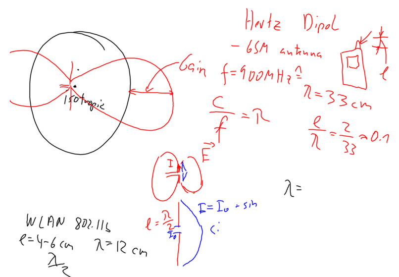
The gain is the radiation intensity of an antenna into the main direction as compared to an isotropic antenna (omnidirectional). For a perfect antenna without any losses, the gain G will be identical to the directivity D.
Antenna pattern
If the antenna pattern is known, then the gain can be easily calculated.
- Isotropic antenna = point source:
- Hertz Dipol = Short dipol:
-
-Dipol:
- draw electrical field of dipole
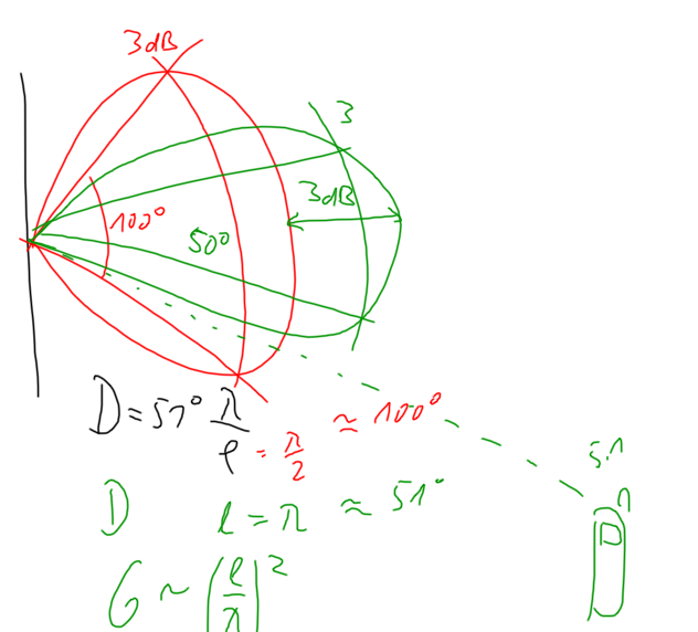
- Aperture antennas:
, with
, leads to gain of
- examples of reflector antennas (effective aperture)
For more info, see intro course: http://www.cv.nrao.edu/course/astr534/AntennaTheory.html
Example:
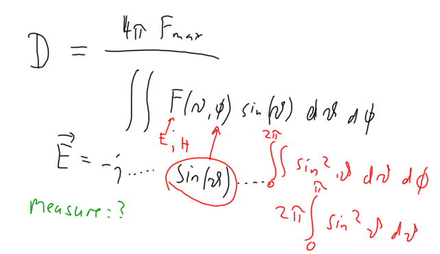
Gain calculation for a -antenna
calculate the gain of a
antenna, given that the electrical field can be described as:
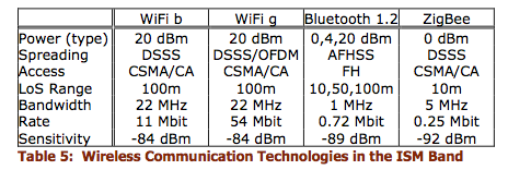
Practical measurement of antenna gain: Compare the value of the electromagnetic field in the main direction of radiation with the gain of an isotropic antenna (or the gain of a known antenna). Best interaction is for antennas with length l approx lambda/2 ... lambda. Examples are provided for stubb antennas on GSM phones and typical WLAN 802.11b antennas.
Calculate the gain of a lambda/2 antenna, given that the electrical field of the antenna is given through a sin(theta) relation
Doubling antenna gain (+3 dB) will decrease the antenna pattern by a factor of two. This might cause mobile phones to fall outside of the radiation range.
Example
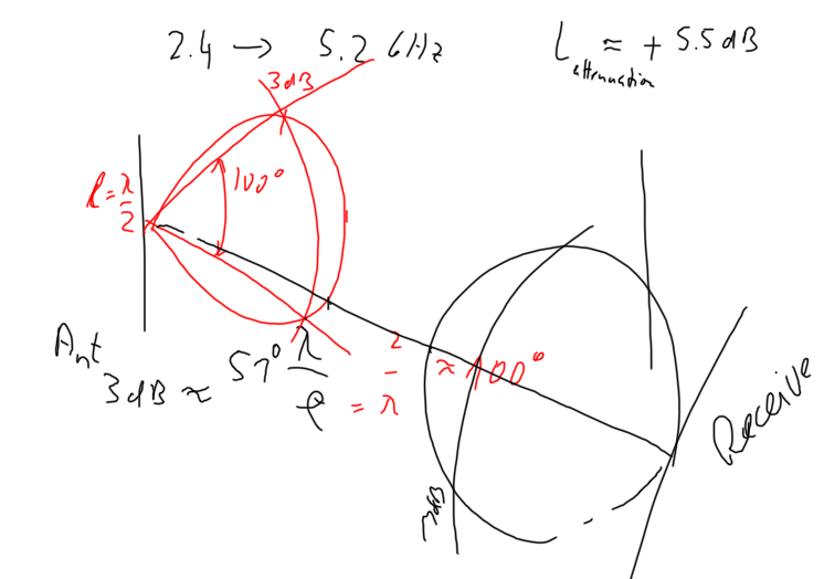
What happens if I move from 2.4 Unik/GHz (802.11b) band to 5.1 Unik/GHz (802.11a)?
- Free space propagation
- antenna gain
- total power budget
- other factors?
Increase frequency from 2.4 to 5.2 Unik/GHz will yield to an additional free-space attenuation of 5.5 dB. If the same antennas are used, then this attenuation will be overcompensated by the antenna gain of both the transmit and the receive antenna.
However, the antenna characteristic will change significantly when doubling the frequency. Assuming that no mismatch occurs at the antenna feed, the width of the antenna beam will be reduced by a factor of two (relation lambda/l). This means that if receive and transmit antennas don't point towards each other, significant antenna gain loss might be seen.
Further Reading
- Media:Antennas_for_communications_Haavard.pdf (by Håvard Austad)
- Book: Stallings; Wireless Communications & networks
- Book:Thorvaldsen & Henne; Planning of line-of-sight radio relay system
- Book:Balanis: Antenna Therory: Analysis and Design
B3-Multipath Propagation
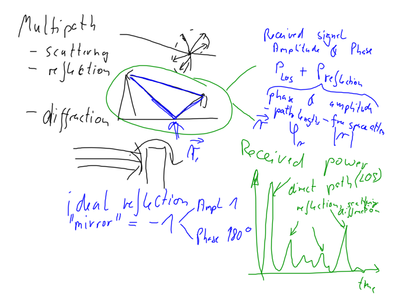
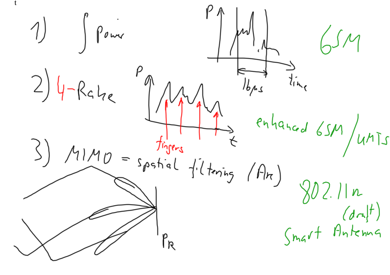
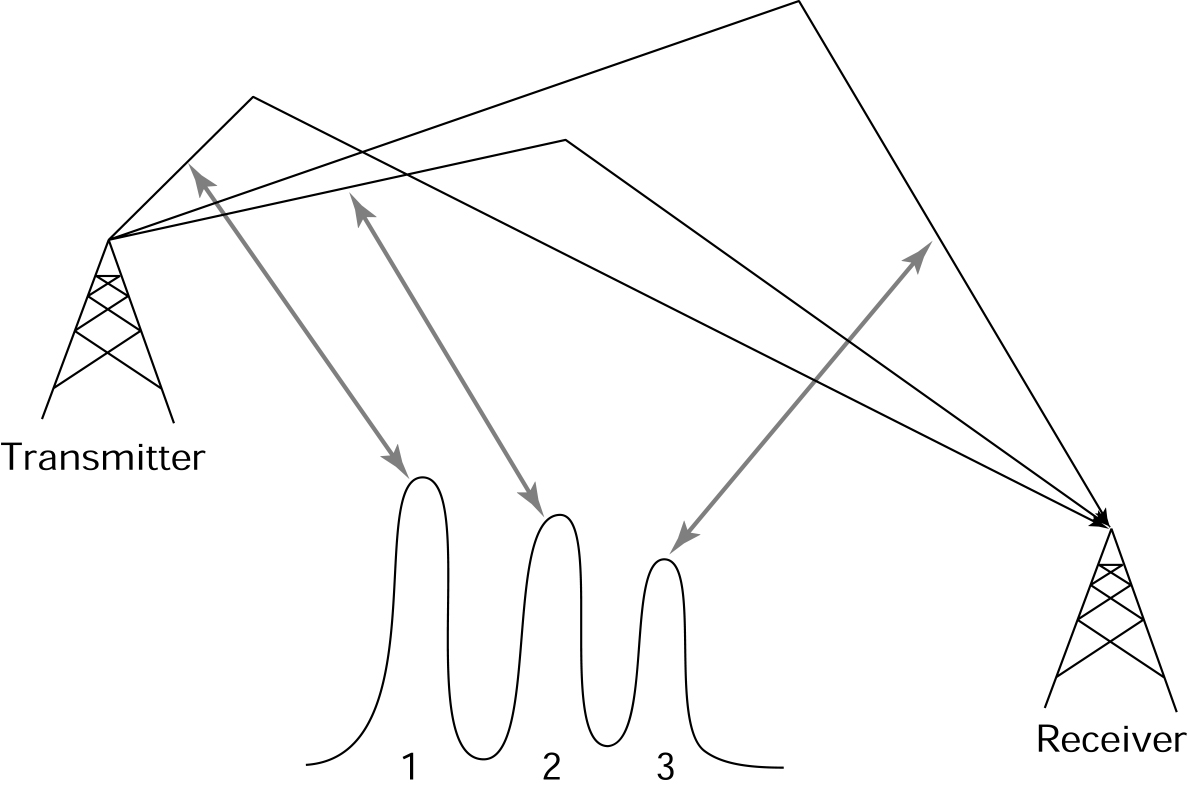
Multipath and how to use it
|
Multipath propagation can be used through
|
Note: The mobile phone users will typically not have a direct link between the mobile phone and the antennas of the base station in a typical environment. Such a situation, where the mobile communication has to go "around a building" or "around the corner" are called NLOS, non Line-of-Sight connection. As compared to a Line-of-Sight LOS connection the signal is typically reduced by some 20-30 dB.
Boundary conditions
Comments
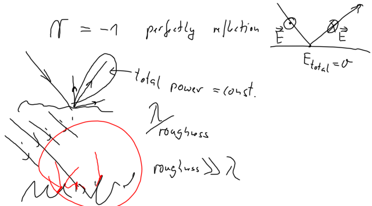
Reflection
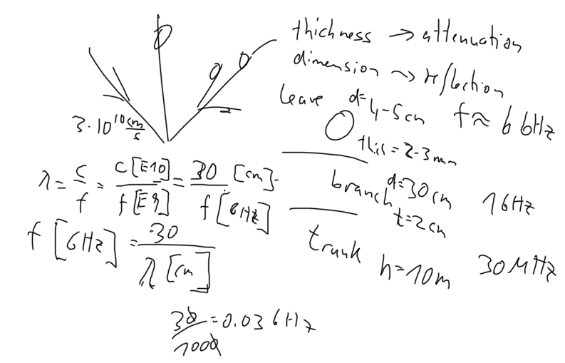
Interaction of electromagnetic waves with the Environment
Examples are:
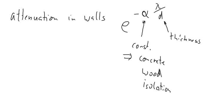
- leaves will mainly interact around 6 Unik/GHz: thickness will attenuate, whereas reflection is due to diameter of leaves
- branches will have main interaction at about 1 Unik/GHz
- the tree trunk will interact with almost all frequencies at 30 Unik/MHz and above.
Attenuation parameters for 2.4 GHz
| Obstacle | Attenuation |
|
|---|---|---|
| Brick wall with window | 2 | |
| Brick wall next to metal door | 3 | |
| Cinder Block wall | 4 | |
| Office wall | 6 | |
| Metal door in office wall | 6 | |
| Metall door in brick wall | 12.4 | |
| Floor | 30 |
Measurements performed for European building
(Source:Hydra Deliverable D5.4, p 12)
