Difference between revisions of "B3-Multipath Propagation"
From its-wiki.no
Josef.Noll (Talk | contribs) |
Josef.Noll (Talk | contribs) |
||
| Line 1: | Line 1: | ||
| + | |||
==⌘Multipath and how to use it== | ==⌘Multipath and how to use it== | ||
{| | {| | ||
| Line 6: | Line 7: | ||
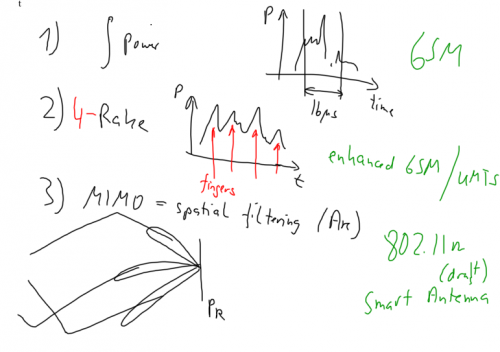
#) Multiple-input, multiple-output antenna systems (MIMO) | #) Multiple-input, multiple-output antenna systems (MIMO) | ||
|} | |} | ||
| + | |||
| + | |||
| + | =⌘ Boundary conditions = | ||
| + | * What is happening on electrical walls, magnetic walls? | ||
| + | |||
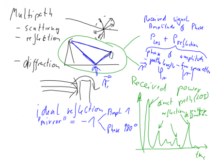
| + | [[File:DirectReflectedWave.png|450px|right|Figure: Reflection of an electromagnetic wave at the ground plane]] | ||
| + | |||
| + | Scattering, reflection and diffraction (<span style="color:#000B80">explain differences</span>) are the three major components in wave propagation. Ideal reflection environments are characterised through <math> |r| =1,\ \ \phi_r=180\deg </math> | ||
| + | |||
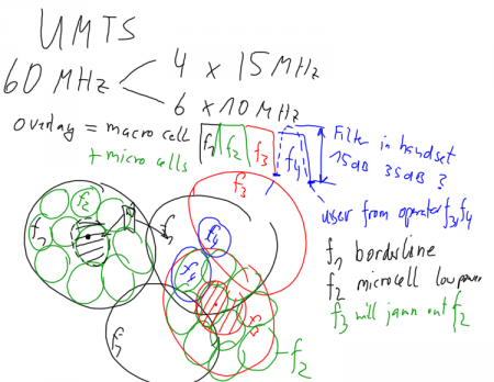
| + | [[File:UMTScells.png|450px|right|Figure: UMTS macro and microcells in a 6-operator environment]] | ||
| + | |||
| + | |||
===⌘Comments=== | ===⌘Comments=== | ||
Revision as of 10:30, 21 September 2014
| Wiki for ITS | ||||||
|---|---|---|---|---|---|---|
|
Contents
⌘Multipath and how to use it
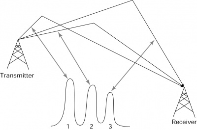
|
Multipath propagation can be used through
|
⌘ Boundary conditions
- What is happening on electrical walls, magnetic walls?
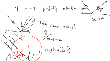
Scattering, reflection and diffraction (explain differences) are the three major components in wave propagation. Ideal reflection environments are characterised through
⌘Comments
⌘ Reflection
Related physics
Free Space impedance as connection of permeability
and permittivity
.
. The unit of
is
. The unit of
is Farad/m:
