Difference between revisions of "Basics of Communication (A1-A3)"
Josef.Noll (Talk | contribs) |
Josef.Noll (Talk | contribs) |
||
| Line 67: | Line 67: | ||
</slideshow> | </slideshow> | ||
</noinclude> | </noinclude> | ||
| + | |||
| Line 82: | Line 83: | ||
* Signal strength | * Signal strength | ||
| − | + | {{:Building Networks/Electromagnetic signals}} | |
| − | + | ||
| − | + | ||
| − | + | ||
| − | + | ||
| − | + | ||
| − | + | ||
| − | + | ||
| − | + | ||
| − | + | ||
| − | + | ||
| − | + | ||
| − | + | ||
| − | + | ||
| − | + | ||
| − | + | ||
| − | + | ||
| − | + | ||
| − | + | ||
| − | + | ||
| − | + | ||
| − | + | ||
| − | + | ||
| − | + | ||
| − | + | ||
| − | + | ||
| − | + | ||
| − | + | ||
| − | + | ||
| − | + | ||
| − | + | ||
| − | + | ||
| − | + | ||
| − | + | ||
| − | + | ||
| − | + | ||
| − | + | ||
| − | + | ||
| − | + | ||
| − | + | ||
| − | + | ||
| − | + | ||
| − | + | ||
| − | + | ||
| − | + | ||
| − | + | ||
| − | + | ||
| − | + | ||
| − | + | ||
| − | + | ||
| − | + | ||
| − | + | ||
| − | + | ||
| − | + | ||
| − | + | ||
| − | + | ||
| − | + | ||
| − | + | ||
| − | + | ||
| − | + | ||
| − | + | ||
| − | + | ||
| − | + | ||
| − | + | ||
| − | + | ||
| − | + | ||
| − | + | ||
| − | + | ||
| − | + | ||
| − | + | ||
| − | + | ||
| − | + | ||
| − | + | ||
| − | + | ||
| − | + | ||
| − | + | ||
| − | + | ||
| − | + | ||
| − | + | ||
| − | + | ||
| − | + | ||
| − | + | ||
| − | + | ||
| − | + | ||
| − | + | ||
| − | + | ||
| − | + | ||
| − | + | ||
| − | + | ||
| − | + | ||
| − | + | ||
| − | + | ||
| − | + | ||
| − | + | ||
| − | + | ||
| − | + | ||
| − | + | ||
| − | + | ||
| − | + | ||
| − | + | ||
| − | + | ||
| − | + | ||
| − | + | ||
| − | + | ||
| − | + | ||
| − | + | ||
| − | + | ||
| − | + | ||
| − | + | ||
| − | + | ||
| − | + | ||
| − | + | ||
| − | + | ||
| − | + | ||
| − | + | ||
| − | + | ||
| − | + | ||
| − | + | ||
| − | + | ||
| − | + | ||
| − | + | ||
| − | + | ||
| − | + | ||
| − | + | ||
| − | + | ||
| − | + | ||
| − | + | ||
| − | + | ||
| − | + | ||
| − | + | ||
| − | + | ||
| − | + | ||
| − | + | ||
| − | + | ||
| − | + | ||
| − | + | ||
| − | + | ||
| − | + | ||
| − | + | ||
| − | + | ||
| − | + | ||
| − | + | ||
| − | + | ||
| − | + | ||
| − | + | ||
| − | + | ||
| − | + | ||
| − | + | ||
| + | {{:Building Networks/Radio Communication principles}} | ||
| − | + | {{:Building Networks/Digital Communication principles}} | |
Revision as of 10:29, 21 September 2014
| Wiki for ITS | ||||||
|---|---|---|---|---|---|---|
|
Basics of Communication (A1-A3)
| Course | UNIK4700, UNIK9700 |
|---|---|
| Title | Basics of Communication and Assignments |
| Lecture date | 2014/09/05 0900-1200 h |
| presented | by Josef Noll |
| Objective | The objective of this lecture is to explain the principles of radio communication |
| Learning outcomes | What will we learn today
|
| Pensum (read before) | Read before: |
| References (further info) | References:
A Practical Evaluation of Radio Signal Strength: Propagation characteristics of wireless channels: |
| Keywords | SNR, Transmit Power, Scattering, Reflection, Diffraction |
this page was created by Special:FormEdit/Lecture, and can be edited by Special:FormEdit/Lecture/Basics of Communication (A1-A3).
Test yourself, answer these questions
- What factors affect Wireless signal strength?
- Explain the meaning of the term diffraction
- How is diffraction used for radio communications?
- What is the difference between diffraction and interference?
- What is the difference between Scattering and Diffraction?
- What is non line of sight (NLOS)?
- Does WiMAX possess NLOS capability?
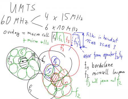
- How is UMTS different from current second generation networks?
Lecture notes
- 2014: Media:UNIK4700h14-Basics_of_Communications.pdf
- Video: mms://lux.unik.no/UNIK4700-JN/UNIK-20140905.wmv
- Assignments: UNIK4700:Assignments
- 2013: Media:UNIK4700-L2H13.pdf
earlier notes
To Do
Towards next lecture:
- Prepare your presentations: UNIK4700:Assignments
- Select papers related to your topics
- Come with a suggestion on the direction of your presentation
- Josef to define a time schedule
- No assignment, talk to Josef!
Test yourself, answer these questions
- What factors affect Wireless signal strength?
- Explain the meaning of the term diffraction
- How is diffraction used for radio communications?
- What is the difference between diffraction and interference?
- What is the difference between Scattering and Diffraction?
- What is non line of sight (NLOS)?
- Does WiMAX possess NLOS capability?
- How is UMTS different from current second generation networks?
- Title
- UNIK4700/UNIK9700 Basics of Propagation
- Author
- Josef Noll,
- Footer
- Basics of Communication (A1-A3)
- Subfooter
- UNIK4700/UNIK9700
⌘ UNIK4700 Radio and Mobility
Lecture 2: Basics of communications
⌘ Principles of radio communication
- radio wave propagation
- Electromagnetic signals
- Nyquist Theorem
- Signal/noise ratio
- Shannon Theorem
- Signal strength
Building Networks/Electromagnetic signals
Building Networks/Radio Communication principles
Building Networks/Digital Communication principles
⌘ Boundary conditions
- What is happening on electrical walls, magnetic walls?
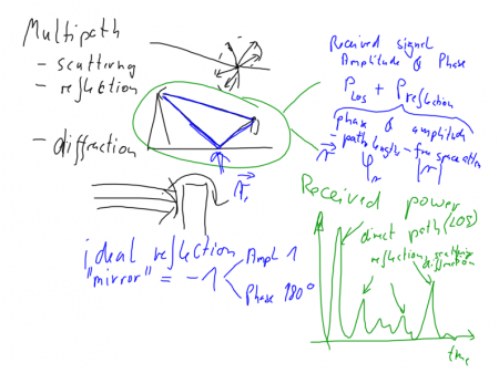
Scattering, reflection and diffraction (explain differences) are the three major components in wave propagation. Ideal reflection environments are characterised through
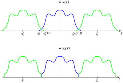
⌘ Nyquist Theorem
- Shannon: If a function
contains no frequencies higher than
[cycles/s], it is completely determined by giving its ordinates at series of points spaced
seconds apart
- band-limitation versus time-limitation
- Fourier transform
[source: Shannon, 1948]
⌘ Signal/noise ratio
,
where P is average power
- why talking about noise?
- dB,
- near-far problem
[source: Wikipedia]
⌘ Shannon Theorem
Shannons theorem will be part of next lexture...
⌘ Summary
- radio wave propagation explain
- Electromagnetic signals
- Nyquist Theorem
- Signal/noise ratio


