Difference between revisions of "C2-Outdoor"
From its-wiki.no
Josef.Noll (Talk | contribs) m (Josef.Noll moved page C2 to C2-Outdoor Communication) |
Josef.Noll (Talk | contribs) |
||
| (One intermediate revision by the same user not shown) | |||
| Line 1: | Line 1: | ||
= ⌘ C2-Outdoor communications = | = ⌘ C2-Outdoor communications = | ||
= ⌘Measurements in rural farmland= | = ⌘Measurements in rural farmland= | ||
| − | * Typical IR from Farm_1, 1718 | + | * Typical IR from Farm_1, 1718 MHz. Total received power was –84 dBm, 20 dB above GSM sensitivity level |
[[File:RakkenLovnesFig16Telektronikk.png|650px]] | [[File:RakkenLovnesFig16Telektronikk.png|650px]] | ||
| Line 18: | Line 18: | ||
==⌘Measurements in cities== | ==⌘Measurements in cities== | ||
| − | * Typical IR from City street measurements, 1950 | + | * Typical IR from City street measurements, 1950 MHz, Oslo. Output power 25 dBm (<span style="color:#000B80"> in mW?</span>). Omnidirectional <math>\lambda/4</math>-Dipoles used as transmit and receive antennas. |
[[File:RakkenLovnesFig28bTelektronikk.png]] | [[File:RakkenLovnesFig28bTelektronikk.png]] | ||
| Line 31: | Line 31: | ||
* Outdoor to indoor and pedestrian test environment, based on Non LOS (NLOS) | * Outdoor to indoor and pedestrian test environment, based on Non LOS (NLOS) | ||
* Base stations with low antenna height are located outdoors, pedestrian users are located on streets and inside buildings and residences | * Base stations with low antenna height are located outdoors, pedestrian users are located on streets and inside buildings and residences | ||
| − | * TX power is 14 dBm, ''f = 2000 | + | * TX power is 14 dBm, ''f = 2000 MHz'' and ''r'' is distance in m |
* Assumes average building penetration loss of 12 dB | * Assumes average building penetration loss of 12 dB | ||
* Path loss model: <math>L_{pedest}=40 \log{r} + 30 \log{f} + 49 </math> [dB] | * Path loss model: <math>L_{pedest}=40 \log{r} + 30 \log{f} + 49 </math> [dB] | ||
| Line 49: | Line 49: | ||
==⌘ETSI vehicular == | ==⌘ETSI vehicular == | ||
* larger cells (typical few km) | * larger cells (typical few km) | ||
| − | * TX power 24 dBm for mobile phone, transmit antenna height <math>\Delta h</math> over roof top (typical 15 m), distance ''r'' in km, ''f = 2000 | + | * TX power 24 dBm for mobile phone, transmit antenna height <math>\Delta h</math> over roof top (typical 15 m), distance ''r'' in km, ''f = 2000 MHz'' |
* Path loss model: <math>L_{vehicular}=40(1-4\cdot 10^{-3}\Delta h) \log{r} - 18 \log{\Delta h} + 21 \log{f} + 80 </math> [dB] | * Path loss model: <math>L_{vehicular}=40(1-4\cdot 10^{-3}\Delta h) \log{r} - 18 \log{\Delta h} + 21 \log{f} + 80 </math> [dB] | ||
Latest revision as of 19:23, 10 September 2018
| Wiki for ITS | ||||||
|---|---|---|---|---|---|---|
|
Contents
⌘ C2-Outdoor communications
⌘Measurements in rural farmland
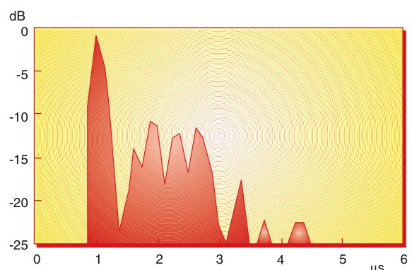
- Typical IR from Farm_1, 1718 MHz. Total received power was –84 dBm, 20 dB above GSM sensitivity level
(Source:R Rækken, G. Løvnes, Telektronikk)
These questions are valid for all of the following impulse responses
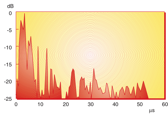
- from delay, calculate reflection factor and free space attenuation
- describe characteristics of reflection
⌘ Measurements in rural farmland
- Typical IR from Farm_2, 953MHz. Total received power was <93dBm
(Source:R Rækken, G. Løvnes, Telektronikk)
⌘Measurements in cities
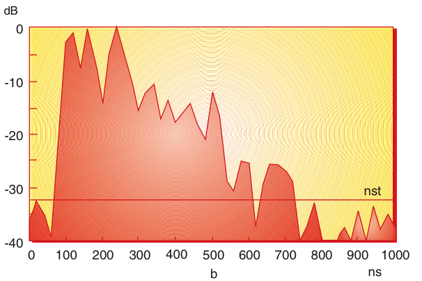
- Typical IR from City street measurements, 1950 MHz, Oslo. Output power 25 dBm ( in mW?). Omnidirectional
-Dipoles used as transmit and receive antennas.
(Source:R Rækken, G. Løvnes, Telektronikk)
why almost equal distribution? What effect?
⌘ETSI urban pedestrian
- Outdoor to indoor and pedestrian test environment, based on Non LOS (NLOS)
- Base stations with low antenna height are located outdoors, pedestrian users are located on streets and inside buildings and residences
- TX power is 14 dBm, f = 2000 MHz and r is distance in m
- Assumes average building penetration loss of 12 dB
- Path loss model:
[dB]
⌘COST Walfish-Ikegami Model
- taking into consideration propagation over roof tops
- assumes antennas below roof top
- Path loss model:
[dB]
⌘Alternative Street Microcell Path-loss
- Outdoor propagation, consists of "adding of paths"
- c is angle of street crossing. c = 0.5 for 90 deg crossing
- k_0 = 1 and d_0 = 0
- Path loss model:
[dB]
- illusory distance
with
⌘ETSI vehicular
- larger cells (typical few km)
- TX power 24 dBm for mobile phone, transmit antenna height
over roof top (typical 15 m), distance r in km, f = 2000 MHz
- Path loss model:
[dB]
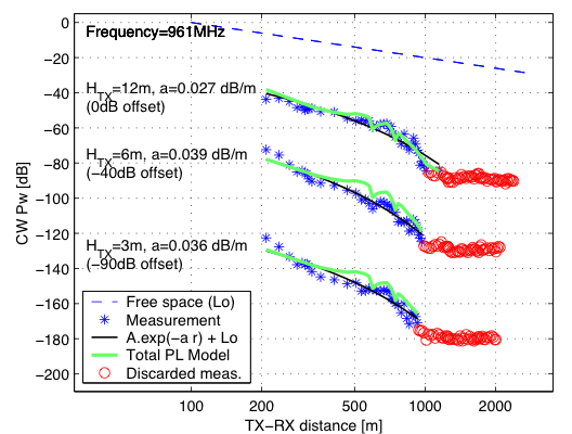
⌘Forest, 961 MHz measurements
- slightly hilly terrain
(Source:István Z.Kovács,Ph.D.Lecture,CPK, September6, 2002;p.27/45 )
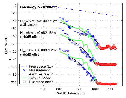
⌘Forest, 1890 MHz measurements
- slightly hilly terrain
(Source:István Z.Kovács,Ph.D.Lecture,CPK, September6, 2002, p.27/45)
⌘Examples
establish table (L free space, pedestrial, outdoor, ...) with typical values for 900 and 2000 MHz and distances from 100 to 3000 m
