Environments for Mobile and Wireless Communications (C1-C3)
| Wiki for ITS | ||||||
|---|---|---|---|---|---|---|
|
Environments for Mobile and Wireless Communications (C1-C3)
| Course | UNIK4700, UNIK9700 |
|---|---|
| Title | Frequency Ranges and Propagation Models for Communications (C1-C3) |
| Lecture date | 2017/10/31 1300-1600 |
| presented | by Josef Noll |
| Objective | The lecture will provide a short overview over propagation models in several environments, e.g. rural and indoor. Typical models are discussed, and references given to future work. The second part of the lecture focusses on the development of your own examples, where a short presentation is expected. |
| Learning outcomes | * get feedback on your topics
|
| Pensum (read before) | Prepare a presentation providing a short overview over your scenario, expected outcome, as well as questions |
| References (further info) | |
| Keywords | Frequency, Propagation Models, Wifi, Mobile Systems |
this page was created by Special:FormEdit/Lecture, and can be edited by Special:FormEdit/Lecture/Environments for Mobile and Wireless Communications (C1-C3).
Presentations
- Lecture notes H16: Media:20161101UNIK4700h16-IR.pdf
Present the first assignments:
- Raul: "Frequency range and type of wireless communications" Media:Frequency_Range_Communications_Raul.pdf
- Yun Ai: "Propagation Models" Media:Propagation_Models_Yun_Ai.pdf, Media:Propagation_Models_Yun_Ai.pptx
- Lecture notes H14: Media:201409UNIK4700h14-Wifi-Propagation.pdf
- Title
- UNIK4700/UNIK9700 Mobile Generations and Radio Models
- Author
- Josef Noll,
- Footer
- Environments for Mobile and Wireless Communications (C1-C3)
- Subfooter
- UNIK4700/UNIK9700
⌘AA2-Mobile Generations
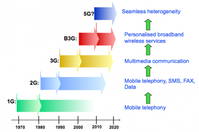
⌘History of wireless communications
while 1G and 2G were all about radio interfaces,
- 3G and Beyond 3G (B3G) are all about services
- 4G is using mobile broadband everywhere
- 5G will be truly heterogeneous network
Comments
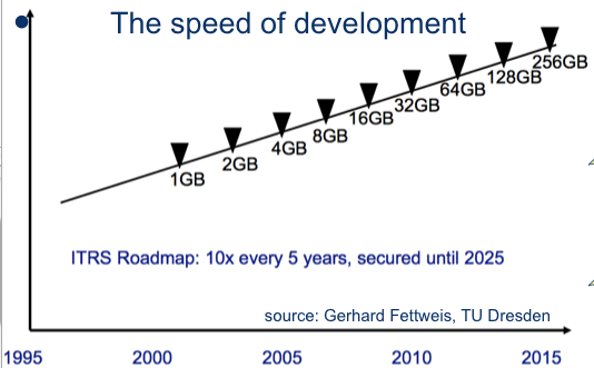
⌘Speed of technology
- "There might be a need for 5 computers" (1943 Watson(?), 1951 Hartree)
- Mobile: NMT, GSM, GPRS, EDGE, UMTS, 3G, HSDPA, SMS, EMS, MMS,... DVB-H,...
Comments
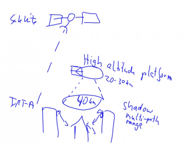 Future communication systems, composed of IMT-A (ground), High altitude platform (HAP) and satellite
%Wireless standardisation forums
- ITU-T
- ETSI
- IEEE
- 3GPP (3G Partnership Project) and 3GPP2
- Bluetooth SIG, zigbee alliance
and a lot of others addressing interworking
- OMA (open mobile alliance)
- UMTS forum
- ...
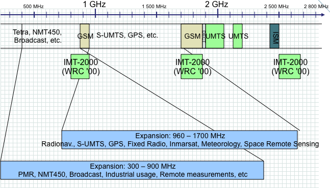
⌘Frequency spectrum
⌘Wireless technologies
Ultra short range
- RFID, NFC
Vicinity
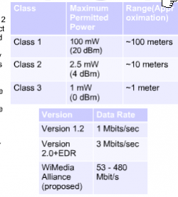
- Bluetooth, WiMedia,
- Zigbee, ANT+, Bluetooth Low Energy (BLE)
Local area
- Wireless LAN, 802.11 family
- Wireless telephony: DECT (Digital Enhanced Cordless Telecommunications)
Mobile Communications:
- 1G: NMT
- 2G: GSM
- 3G: UMTS
- 4G: LTE - IMT-A
- 5G
Long Range Wide Area Network (LPWAN)
- LoRa,
- Sigfox,
- Ingenu-RPMA,
- DASH7,
- Weightless
Mobile satellite communication:
- Geostationary (Inmarsat A, C, M) or low orbit (e.g. Iridium)
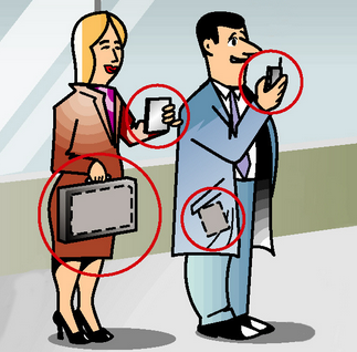
⌘Trend: Personal Networks
Interconnectivity
|
⌘Expectations towards global coverage
- According to Ericsson, Mobile Technologies are available for 50% of the world's population (2013), and the coverage will increase to 75% by 2017.
- According to Internet.org (Facebook, Opera Software, ....), only 1/3 of the world's population has access to the Internet (2013).
- An extrapolation by the Basic Internet Foundation points out that even in 2017 about 45% of the population will not have access to Internet, mainly due to affordability. Thus they promote the free access to basic information of the Internet, being text and pictures.
⌘Propagation scenario (ITU-R)
| Radio coverage [km2] | Distance [km] | speed of mobile [km/h] | type of cell | |
| Indoor office environment | 0.01 | 0.1 | 3 | picocell in open space environment |
| Pedestrian mode | 4 | 2 | 3 | Microcell |
| Vehicle | 150 | 13 | 120 | Macrocell |
- see page 31 of ETSI TR 101 120 report for test environments
- impact on walls?
⌘Propagation models
- Environments (indoor, outdoor to indoor, vehicular)
- outside (Lee, Okumura, Hata, Unik/COST231-Hata, Unik/COST231-Walfish-Ikegami)
- inside (One-slope, multiwall, linear attenuation)
References:
- T.K. Sarkar, J. Zhong, K. Kyungjung, A. Medouri, M. Salazar-Palma, "A survey of various propagation models for mobile communications", IEEE Ant. Prop. Magazine, 2003, 45(3) 51-82
- M Hata, "Empirical formula for propagationloss in land mobile radio service". IEEE Trans Vehicular Technology, 1980, vol 29, pp 317-325
- F Ikekami, S Yoshida, T Takeuchi, M Umehira, "Propagation factors controlling mean field strength on urban streets", IEEE Trans Ant. Prop., 1984, 32(8), 822-829
- T.S. Rappaport, S. Sandhu, "Rdaio Wave propagation for Emergin Wireless Personal Communication Systems", IEEE Ant. Prop. Magazine, 1994, 36(5), 14-23
we will focus only on ETSI models: statistical models to generate path losses and time delay structures for paths in each test environment.
(Source: Cost259, page 80ff, and ETSI TR 101 120)
⌘ Mobile Propagation References
References:
- Eurescom P921: UMTS radio access, http://www.eurescom.de D2-UMTS radio access
- ETSI / ITU propagation channels (Vehicular A/B, Outdoor to indoor A/B)
⌘ C2-Outdoor communications
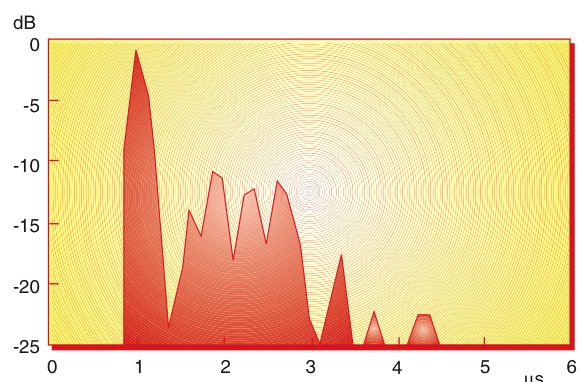
⌘Measurements in rural farmland
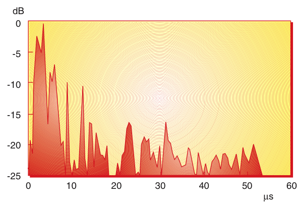
- Typical IR from Farm_1, 1718 MHz. Total received power was –84 dBm, 20 dB above GSM sensitivity level
(Source:R Rækken, G. Løvnes, Telektronikk)
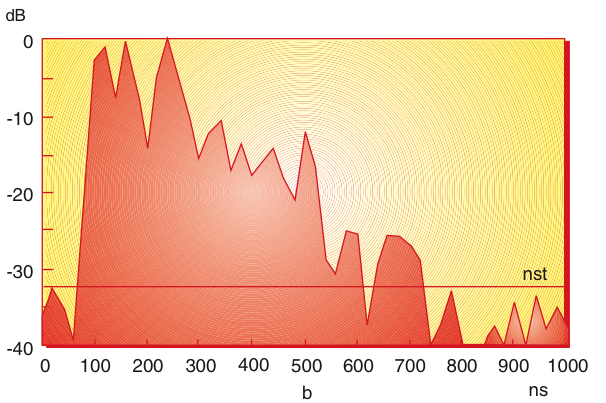
These questions are valid for all of the following impulse responses
- from delay, calculate reflection factor and free space attenuation
- describe characteristics of reflection
⌘ Measurements in rural farmland
- Typical IR from Farm_2, 953MHz. Total received power was <93dBm
(Source:R Rækken, G. Løvnes, Telektronikk)
⌘Measurements in cities
- Typical IR from City street measurements, 1950 MHz, Oslo. Output power 25 dBm ( in mW?). Omnidirectional
-Dipoles used as transmit and receive antennas.
(Source:R Rækken, G. Løvnes, Telektronikk)
why almost equal distribution? What effect?
⌘ETSI urban pedestrian
- Outdoor to indoor and pedestrian test environment, based on Non LOS (NLOS)
- Base stations with low antenna height are located outdoors, pedestrian users are located on streets and inside buildings and residences
- TX power is 14 dBm, f = 2000 MHz and r is distance in m
- Assumes average building penetration loss of 12 dB
- Path loss model:
[dB]
⌘COST Walfish-Ikegami Model
- taking into consideration propagation over roof tops
- assumes antennas below roof top
- Path loss model:
[dB]
⌘Alternative Street Microcell Path-loss
- Outdoor propagation, consists of "adding of paths"
- c is angle of street crossing. c = 0.5 for 90 deg crossing
- k_0 = 1 and d_0 = 0
- Path loss model:
[dB]
- illusory distance
with
⌘ETSI vehicular
- larger cells (typical few km)
- TX power 24 dBm for mobile phone, transmit antenna height
over roof top (typical 15 m), distance r in km, f = 2000 MHz
- Path loss model:
[dB]
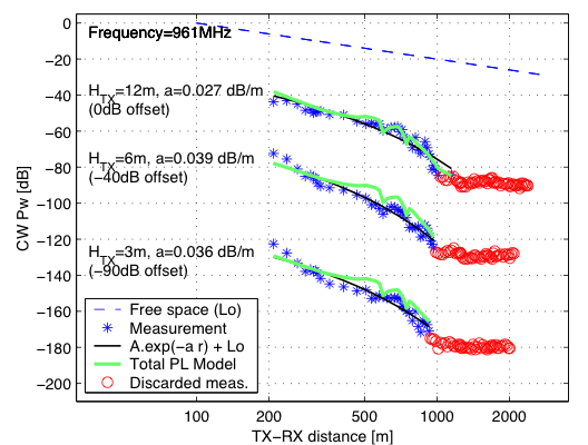
⌘Forest, 961 MHz measurements
- slightly hilly terrain
(Source:István Z.Kovács,Ph.D.Lecture,CPK, September6, 2002;p.27/45 )
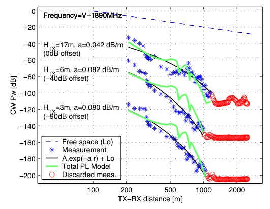
⌘Forest, 1890 MHz measurements
- slightly hilly terrain
(Source:István Z.Kovács,Ph.D.Lecture,CPK, September6, 2002, p.27/45)
⌘Examples
establish table (L free space, pedestrial, outdoor, ...) with typical values for 900 and 2000 MHz and distances from 100 to 3000 m
⌘ETSI Indoor Office test environment
- derived from COST 231
- r is transmitter-receiver distance in m; n is number of floors in the path
- path loss L should always be more than free space loss. Log-normal shadow fading standard deviation of 12 dB
- Path loss model:
[dB]
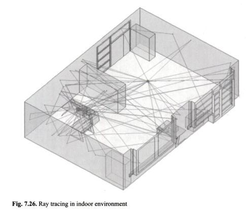
⌘Modelling approach - indoor
Typical ETSI parameters: 8 kbps, BER < 10'^-3^', 20 ms delay, 50 % activity
(Source:Radio Wave Propagation for Telecommunication, Springer, and ETSI TR 101 112 V3.2.0 (1998-04))
Next lecture D1 Proximity Systems such as NFC, RFID
⌘ Mobile Communication Spectrum
|
Source: http://www.spectrum2020.ca/presentations/Rappaport.pdf |
⌘ The challenge of area coverage
Land area Norway, 385.178 km^2 - 7500 basestasjons http://www.mynewsdesk.com/no/telenor/pressreleases/sjekk-naar-du-faar-4g-der-du-bor-1399662
- Tanzania 947,303 km^2 = 3 x Norway,
- Mali 1.240.000 km^2 = 4 x Norway
- DRC 2.345.000 km^2 = 8 x Norway
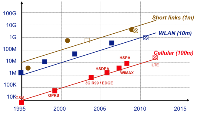
⌘ Throughput increase
[Presentation G. Fettweis, IEEE VTC forum Baltimore], http://www.ieeevtc.org/plenaries/vtc2007fall/28.pdf
⌘Example of propagation
Results for UMTS (worst case), with 3 sector antenna
- Range of unloaded cell is 700 m in urban pedestrian
- With loaded cell, assumed increase of noise by 10 dB, max cell radius 390 m
- vehicular with typical range of 3600 m (unloaded) and 1900 m (loaded)
- Next: examples and simulations
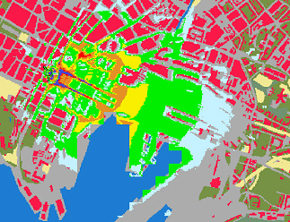
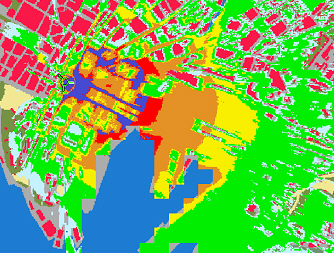
⌘Oslo simulations, performed for GSM at 1800 MHz
how much does the range decrease when reducing the power by 10 dB?
(Source: Helge Dommarsnes, Telenor Mobil)
⌘Difference GSM - UMTS
- Frequency
- Receiver structure
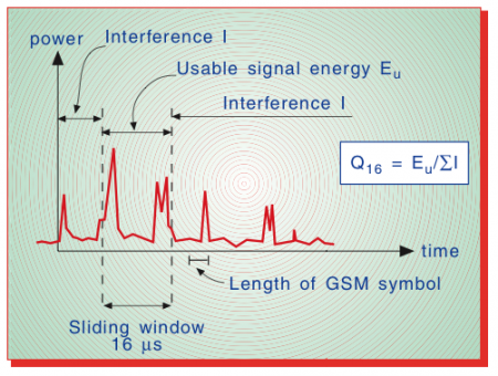
- GSM sliding window of 16
- UMTS Rake receiver
- GSM sliding window of 16
Q16ratio:The ratio of the power inside to the power outside a window of duration 16 . For each IR the window is slid to find the position with highest power inside the window.
(Source:R Rækken, G. Løvnes, Telektronikk)
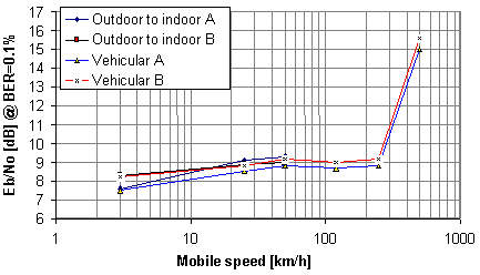
⌘Results of link level simulation
Simulations to achieve minimum W-CDMA using given QoS parameter: here voice service
(Source: Eurescom P921, D2)
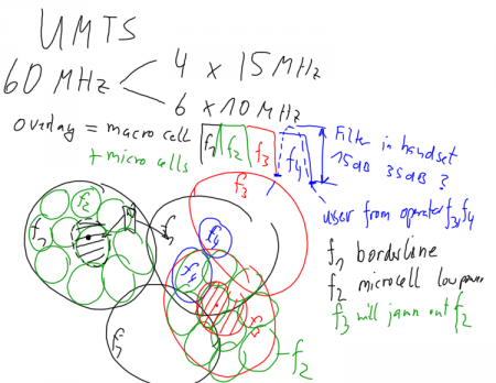
⌘UMTS cell planning
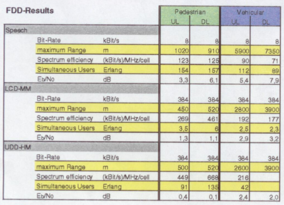
⌘UMTS traffic simulations
Note: voice, Low constraint delay (LCD, typical streaming) and Unconstrained data delay (UDD, typical ftp, email)
(Source:Telenor FoU report 3-99)
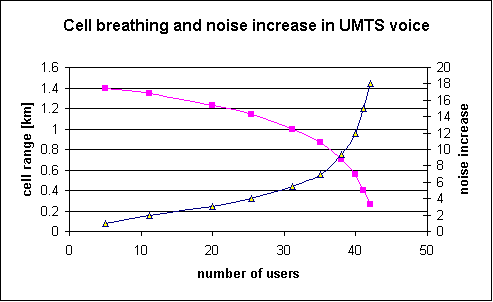
⌘Cell Breathing effect in UMTS
View: http://www.eurescom.de/~public-web-deliverables/P900-series/P921/D2/index.html for "live simulation" and "Cell Ranges for GSM1800 and UMTS Services"
(Source: Eurescom P921, D2)
⌘Network planning
GSM versus UMTS
- UMTS is interference limited
- GSM is build on frequency reuse in the cells, while UMTS has the same frequency in neighbouring cells
- UMTS range is capacity limited
- UMTS requires simultaneous cell planning and network dimensioning
- handover is network based, the handset announces, network performs the handover
- In UMTS a mobile phone can be connected to two cells at the same time, the handover is then called soft handover. Handover between sectors in of the same antenna are called softer handover
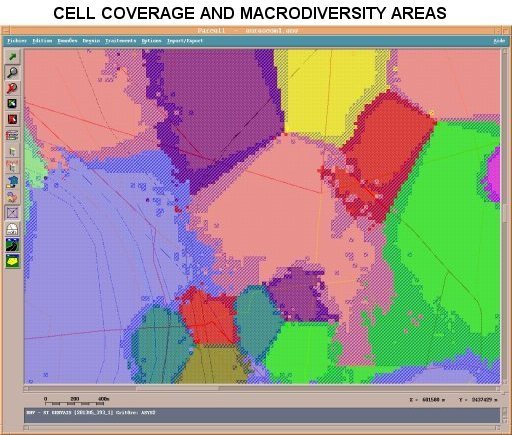
⌘Cell cover and macro-diversity areas
Outcome of Eurescom P921 system level simulations
(Source: Eurescom P921, D2)
⌘Smart antennas and MIMO measurements
GSM
Example GSM: the upload band is from 880-915 Unik/MHz (in Europe), which is 35 Unik/MHz. With a carrier of 200 kHz we have 175 channels, which have to be divided between the various operators.
UMTS specifications
http://www.umtsworld.com/technology/wcdma.htm
⌘4G/LTE technology
- OFDMA based, time, frequency and code scheme, see: https://www.youtube.com/watch?v=Lu4I0iWhmZM
- see: https://www.youtube.com/watch?v=QEpxtiN8Trc (from OFDM to OFDMA)
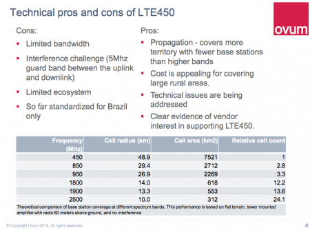
⌘LTE 450 MHz
LTE 450 pro's and con's from Ovum conf. publication (.pdf)
- Band 31, limited bandwidth of 2 x 10 MHz
⌘ IMT-A (4G): WiMAX, LTE
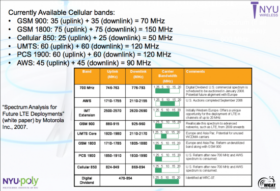
IMT-Advanced (IMT-A) is often called the 4G standard for Mobile Communications. Both WiMAX through the 802.16e and LTE provide technologies for achieving higher data throughput.
Though LTE was originally designed to work in the
Evolution of radio spectrum, and frequency bands for LTE http://www.radio-electronics.com/info/cellulartelecomms/lte-long-term-evolution/lte-frequency-spectrum.php
LTE FDD band, source:radioelectronics.com
LTE TDD band, source: radioelectronics.com
Presentations from earlier courses
WIMAX
- Media:WIMAX.pdf (by Dag Ove, 2012)
- File:Achieving Wireless Broadband with WiMax.pdf
- Media:IEEE 802.16 Standards - The working group and documents.pdf
- Media:Sleep Mode Operation - WiMax.pdf
- Media:The WiMax IEEE 802.16e Physical Layer Model.pdf
- Media:Wimax - Current Performance Benchmarks and Future Potensial.pdf
⌘Verizon Wireless reveals LTE speeds
- from Mobile Business Briefing 7 December 2009
- Verizon Wireless: average downlink 5-12 Mb/s and uplink 2-5 Mb/s (LTE)
⌘Unstrung.com - Wireless News, 24 Nov 2009
11:20 AM -- Four Finnish operators got some Long Term Evolution (LTE 2.6 GHz) and WiMax spectrum for just €3.8 million (US$5.6 million). (See Finland Awards 4G Spectrum.)
- LTE FDD Elisa Corp. bid €834,700 ($1.2 million) for 50 MHz;
- TeliaSonera AB (Nasdaq: TLSN) bid €819,200 ($1.2 million) for 50 MHz; and
- DNA Oy bid € 675,700 ($1 million) for 40 MHz.
- WiMax spectrum (TDD, now LTE TDD), Pirkanmaan Verkko Oy bid € 1,468,200 ($2.2 million) for 50 MHz.
Nordic:
- Norway 229 million Norwegian Kronor ($41 million) in 2007
- Sweden 2 billion Swedish Kronor ($304 million) in 2008.
Sources: See Craig Goes to Norway, Sweden Awards 4G Spectrum, Swedish 4G, Telenor to Test Huawei LTE, and TeliaSonera: We'll Do 4G in 2010
⌘Norway: NPT license conditions
from: [Norwegian Post Telecommunication Regulator (NPT) http://www.npt.no/portal/page/portal/PG_NPT_NO_NO/PAG_NPT_NO_HOME/PAG_RESSURSER_TEKST?p_d_i=-121&p_d_c=&p_d_v=104880]
- 2500-2690 MHz and 2010-2025 MHz. The new licenses expire 31 December 2022.
- five sub-bands, each consisting of a number of contiguous frequency blocks.
- six different regions.
The five sub-bands are:
- (A) The 2010 MHz band, consisting of a single 15MHz block.
- (B) Five unpaired blocks of 10MHz at the centre of the 2.6GHz band (2570 MHz to 2620 MHz).
- (C) Eight paired blocks of 2x5 MHz in the 2.6 GHz band (2500-2540 MHz paired with 2620-2660 MHz).
- (D) Three unpaired blocks of 10 MHz below sub-band B in the 2.6 GHz band (2540-2570 MHz).
- (E) Three unpaired blocks of 10 MHz at the top end of the 2.6 GHz band (2660-2690 MHz)
Note: Unpaired is TDD operation, while paired is FDD operation
⌘ Price policy
The total amount will consist of
- a fixed component per contiguous spectrum block
- a variable component that will depend on the bandwidth at disposal and the population in the geographical area
- Estimate for 2008
- annual administrative charge of (NOK 25000 x number of contiguous blocks)
- + (NOK 1600 x bandwidth in MHz) x (regional percentage of Norway';s population).
<green>Q: take the Norwegian population and calculate the licence costs per region</green>
